Aug 31, 2010

How Does Well Control Work?


Blowouts are easily the most dangerous and destructive potential disasters in the world of oil drilling. Not only can they lead to serious injury and even death, but they can also cause massive, debilitating production shut-downs and can have a negative effect on future production from the lost well. Blowouts can also cause severe ecological damage. As with any potential disaster, prevention is the first step in avoiding an otherwise costly and dangerous situation. These preventative measures are called, collectively, Well Control.
"A clearer phrase [than Well Control] might be Blowout Prevention," said Barry Cooper of Well Control School, an organization, which has offered well control training programs to the oil and gas industry for more than 25 years. "Blowout Prevention is simply the training and understanding of how to prevent this from happening."
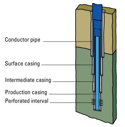
Blowout prevention is a very broad term that can encompass anything from the precautionary methods used on rigs to prevent "kicks" -- the unexpected and undesired flow of formation fluids into a well -- from developing, to the use of sophisticated devices called Blowout Preventers (or BOPs) designed to close off a well in the face of a looming blowout.
The first stage of blowout prevention is preparedness. Most countries and corporations require certification in well control practices from all drilling employees, a policy that underscores the potential danger of a blowout.
To prevent kicks, drilling operators must use "drilling mud," otherwise known as drilling fluid, a viscous mud-like substance that comes in varying densities, to balance the tremendous upward pressure of the formation fluids surging up the well. The downward pressure of the drilling fluid is called bottomhole pressure. Drilling fluid engineers must be vigilant and careful to ensure that the pressures reach equilibrium, a tedious but vitally important task.
"The working [drilling] fluid in a well is considered the primary barrier against blowouts," explained Cooper. "Theoretically, if the formation pressure is greater than the bottomhole pressure, formation fluids could enter a well and, if uncontrolled, develop into a blowout."
BOPs
Should a kick develop, though, there are several fail-safes in place. These heavy, specialized devices are called Blowout Preventers (BOPs). BOPs are essentially large valves on the surface of the well which quickly shut off the well as a last-ditch precaution to prevent a kick from becoming a blowout. Often, different types of BOPs are used in an arrangement configuration, called a "BOP stack."
BOPs come in two main types: annular preventers and ram preventers. Ram preventers move two opposing rods horizontally across the top of the well. Ram blocks on the ends of the shafts create a seal around the pipe. Ram blocks come in various sizes and designs to cope with specific drilling operations.
Annular preventers use an elastomer packer squeezed across the annulus (the void in the well through which drilling fluid is circulated) in a smooth upward-and-inward motion to cork the well and prevent upward movement in the wellbore.
"[Annular preventers] are usually the preventer of choice because the packer will form a seal around any diameter tubular or wireline that may be in the well at the time a kick is taken," said Cooper. However, both types are usually employed in stacks, highlighting the seriousness with which safety is taken where blowouts are concerned.
It is vitally important to recognize and address the situation as quickly and safely as possible, and then act accordingly.
"The great challenge for the crew is recognizing a developing well control incident and taking appropriate action," 

How Do 4-D and 4-C Seismic Work?


Used to find oil and gas prospects, there are multiple types of seismic surveys that can be produced over reservoirs to understand the subsurface environment. Made up of reflection and refraction mapping, seismic surveys give geologists a better idea of what lies beneath the surface - or even below thousands of feet of water.
One of the most intricate forms of seismic survey, 4-D (four-dimensional) seismic, is a type of geophysics. Also known as time lapse seismic, 4-D seismic incorporates numerous 3-D seismic surveys over the same reservoir at specified intervals of time. Studying multiple time-lapsed 3-D surveys, or three-dimensional subsurface images, portrays the changes in the reservoir over time.
Changes in a Reservoir Seen through 4-D Seismic
Changes in a Reservoir Seen through 4-D SeismicSource: Schlumberger
Four-D seismic can determine changes in flow, temperature, pressure and saturation. By scanning a reservoir over a given period of time, the flow of the hydrocarbons within can be traced and better understood. For example, as hydrocarbons are depleted from a field, the pressure and composition of the fluids may change. Additionally, geologists are interested in understanding how the reservoir reacts to gas injection or water flooding. Furthermore, 4-D seismic can help to locate untapped pockets of oil or gas within the reservoir.
Typically, 4-D seismic data is processed by subtracting the data from one survey from the data of another. The amount of change in the reservoir is defined by the difference between the two. If no change has occurred over the time period, the result will be zero.
Another Four-Dimensional Survey: 4-C Seismic
In addition to 4-D seismic, 4-C seismic encompasses multi-component seismic exploration, outlining both compressional and shear waves given off by a seismic source.
Seismic Vessel Performing a 4-C Seismic Survey
Seismic Vessel Performing a 4-C 
Seismic Survey
Source: ATSE
While a compressional wave, also known as a P-wave, is how sound travels through the air, where particles travel closer and then farther apart; a shear wave, or S-wave, is similar to an ocean wave, where the particles actually move up and down.
P-waves travel at a higher rate of speed, and unlike S-waves, P-waves are able to pass through liquids and gases. While compressional waves are distorted by gas in the reservoir, shear waves are not affected, making shear waves a better measurement to determine gases in the sedimentary rocks.
Four-C seismic is used to pinpoint and determine the locations of subsurface fractures, as well as define the make-up of the sedimentary rock layers and their corresponding fluids.

Shape-shifting UAV designed for stormy sea rescues


People often need to be rescued at sea because of stormy weather – exactly the kind of conditions in which it is not safe to fly. Nonetheless, fully-crewed helicopters and fixed-wing aircraft are regularly sent out into such weather to perform maritime rescues, endangering both the crew and the expensive aircraft themselves. Soon, however, a new type of unmanned remote-control aircraft may be able to do the job. Not only would flight crews be kept out of harm’s way, but as demonstrated by a functioning prototype, the aircraft would outperform conventional planes in rough weather, thanks to shape-shifting technology.
The maritime rescue UAV (unmanned aerial vehicle) is being developed through the EUREKA E! 3931 ASARP project, EUREKA being a European intergovernmental network that supports market-oriented research and development.
The prototype seaplane can take off or land on ground or water, fly for up to 4.5 hours, and has a payload capacity of 40 kg. (88 lbs.). It also has onboard cameras which transmit live to its self-sufficient ground command center, where a human operator mans the controls. Presumably it can’t pluck people out of the sea, but it could establish their location and perhaps drop supplies.
The little airplane is able to withstand rough conditions thanks to three aeroservoelastic trim tabs, which are located on the trailing edges of the wings and tail. When the plane is hit by wind gusts, the tabs perform rapid high-frequency shape changes, to counteract the effects of the wind. The technology is not unlike the shape-changing trailing edge flaps currently being developed to protect wind turbines from destructive gusts. Combined with several other features, such as a special aerofoil profile optimized for high lift at low speeds, the result is a remarkably steady aircraft.
The project is being coordinated by GGD Engineering of Scotland, with the tabs being developed by the Computational Fluid Dynamics Centre in Israel. The prototype is currently in the final stages of testing in Cyprus.

Aug 30, 2010

How Does Directional Drilling Work?


Directional drilling has been an integral part of the oil and gas industry since the 1920s. While the technology has improved over the years, the concept of directional drilling remains the same: drilling wells at multiple angles, not just vertically, to better reach and produce oil and gas reserves. Additionally, directional drilling allows for multiple wells from the same vertical well bore, minimizing the wells' environmental impact.
Directional Drilling
Directional DrillingSource: Amerex Co.
Improvements in drilling sensors and global positioning technology have helped to make vast improvements in directional drilling technology. Today, the angle of a drillbit is controlled with intense accuracy through real-time technologies, providing the industry with multiple solutions to drilling challenges, increasing efficiency and decreasing costs.
Tools utilized in achieving directional drills include whipstocks, bottomhole assembly (BHA) configurations, three-dimensional measuring devices, mud motors and specialized drillbits.
Now, from a single location, various wells can be drilled at myriad angles, tapping reserves miles away and more than a mile below the surface.
Directional Drilling
Directional DrillingSource: Mackenzie Gas Project
Many times, a non-vertical well is drilled by simply pointing the drill in the direction it needs to drill. A more complex way of directional drilling utilizes a bend near the bit, as well as a downhole steerable mud motor. In this case, the bend directs the bit in a different direction from the wellbore axis when the entire drillstring is not rotating, which is achieved by pumping drilling fluid through the mud motor. Then, once the angle is reached, the complete drillstring is rotated, including the bend, ensuring the drillbit does not drill in a different direction from the wellbore axis.
One type of directional drilling, horizontal drilling, is used to drastically increase production. Here, a horizontal well is drilled across an oil and gas formation, increasing production by as much as 20 times more than that of its vertical counterpart. Horizontal drilling is any wellbore that exceeds 80 degrees, and it can even include more than a 90-degree angle (drilling upward).

How Does Well Completion Work?


Once a well has been drilled, the decision must be made: Will this well become a producer or be plugged and abandoned as a dry hole? Should the operator decide to move forward with developing the well, completion operations must be undertaken.
Well completion incorporates the steps taken to transform a drilled well into a producing one. These steps include casing, cementing, perforating, gravel packing and installing a production tree.
Casing
The first step in completing a well is to case the hole. After a well has been drilled, should the drilling fluids be removed, the well would eventually close in upon itself. Casing ensures that this will not happen while also protecting the wellstream from outside incumbents, like water or sand.
Consisting of steel pipe that is joined together to make a continuous hollow tube, casing is run into the well. The different levels of the well define what diameter of casing will be installed. Referred to as a casing program, the different levels include production casing, intermediate casing, surface casing and conductor casing.
Additionally, there are two types of casing that can be run on a well. One type of casing consists of a solid string of steel pipe. Solid casing is run on the well if the formation is firm and will remain that way during the life of the well. Should the well contain loose sand that might infiltrate the wellstream, the casing is installed with a wire screen liner that will help to block the sand from entering the wellbore.
Cementing
The next step in well completion involves cementing the well. This includes pumping cement slurry into the well to displace the existing drilling fluids and fill in the space between the casing and the actual sides of the drilled well.
Consisting of a special mixture of additives and cement, the slurry is left to harden, sealing the well from non-hydrocarbons that might try to enter the wellstream, as well as permanently positioning the casing into place.
Open-Hole Completions
At the reservoir level, there are two types of completion methods used on wells: open-hole or cased-hole completions. An open-hole completion refers to a well that is drilled to the top of the hydrocarbon reservoir. The well is then cased at this level, and left open at the bottom. Also known as top sets and barefoot completions, open-hole completions are used to reduce the cost of casing where the reservoir is solid and well-known.
Perforation
Cased-hole completions require casing to be run into the reservoir. In order to achieve production, the casing and cement are perforated to allow the hydrocarbons to enter the wellstream.
Perforation
This process involves running a perforation gun and a reservoir locating device into the wellbore, many times via a wireline, slickline or coiled tubing. Once the reservoir level has been reached, the gun then shoots holes in the sides of the well to allow the hydrocarbons to enter the wellstream. The perforations can either be accomplished via firing bullets into the sides of the casing or by discharging jets, or shaped charges, into the casing.
While the perforation locations have been previously defined by drilling logs, those intervals cannot be easily located through the casing and cement. To overcome this challenge, a gamma ray-collar correlation log is typically implemented to correlate with the initial log run on the well and define the locations where perforation is required.
Gravel Pack
Some wells require filtration systems in order to keep the wellstream clear of sand. In addition to running a casing with a liner, gravel packing is used to prevent sand from entering the wellstream.
More complicated than cementing a well, gravel packing requires a slurry of appropriately sized pieces of coarse sand -- or gravel -- to be pumped into the well between the slotted liner of the casing and the sides of the wellbore. The wire screens of the liner and the gravel pack work together to filter out the sand that might have otherwise entered the wellstream with the hydrocarbons.
Production Tree
The last step in completing a well, a wellhead is installed at the surface of the well. Many times called a production tree or Christmas tree, the wellhead device includes casingheads and a tubing head combined to provide surface control of the subsurface conditions of the well.
Production Tree
Production TreeSource: Cameron
While both onshore and offshore wells are completed by production trees, offshore wells can be completed by two different types of trees: dry and wet trees. Similar to onshore production trees, dry trees are installed above the water’s surface on the deck of a platform or facility and are attached to the well below the water. Wet trees, on the other hand, are installed on the seabed and encased in a solid steel box to protect the valves and gages from the elements. The subsea wet tree is then connected via electronic or hydraulic settings that can be manipulated from the surface or via ROVs.
Additionally, wells may have production flowing from multiple reservoir levels. These wells require multiple completions, which keep the production separate. Double-wing trees are installed on multiple reservoir levels.
Furthermore, completions have evolved to incorporate downhole sensors that measure flow properties, such as rate, pressure and gas-to-oil ratio. Known as intelligent wells or smart wells, these completions help to achieve optimum production rates.

How Does Casing Work?


Once a well has been drilled, if it is to become a production well, the well must undergo completion. While drilling a well cuts through the rock formations and allows drilling engineers to reach the reservoir below, the raw sides of the well cannot support themselves. Similar to the bones of your spine protecting the spinal cord, casing is tubing that is set inside the drilled well to protect and support the wellstream.
In addition to providing stabilization and keeping the sides of the well from caving in on themselves, casing protects the wellstream from outside contaminants, as well as any fresh water reservoirs from the oil or gas that is being produced.
Also known as setting pipe, casing a well involves running steel pipe down the inside of a recently drilled well. The small space between the casing and the untreated sides of the well is filled with cement to permanently set the casing in place.
Casing A Well
The casing is fabricated in sections, or joints, that are usually about 40 feet long and screwed together to form longer lengths of casing, called casing strings. Each end of the casing joint has male threads that are protected by cap called a thread protector until the casings are ready to be jointed. Then, a collar or coupling, composed of a short cylindrical steel pipe that is slightly larger in diameter than the joints and also has female threads, is used to connect the two male joint ends. A thread compound is used on the two ends to ensure a tight seal.
Casing is run from the rig floor, connected one joint at a time by casing elevators on the traveling block and stabbed into the previous casing string that has been inserted into the well. Hanging above the drill floor, casing tongs screw each casing joint to the casing string.
Casing is run into the well and officially landed when the weight of the casing string is transferred to the casing hangers, which are located at the top of the well and use slips or threads to suspend the casing in the well.
A rounded section of pipe with an open hole on the end, a guide shoeis connected to the first casing string to guide the casing crew in running the casing into the well. Additionally, the outside of the casing has spring-like centralizers attached to them to help position in casing string in the center of the well.
After running the casing and before the cementing the well, a useddrill bit is inserted into the well via a drillstring, and drilling fluid is then circulated for a certain amount of time to remove any remaining cuttings from the well. Also wall scratchers are dispatched into the well to remove any filter cake that may have formed on the sides of the well.
A cement slurry is then pumped into the well and allowed to harden to permanently fix the casing in place. After the cement has hardened, the bottom of the well is drilled out, and the completion process continues.
Casing Programs
Sometimes the well is drilled in stages called a casing program. Here, a well is drilled to a certain depth, cased and cemented, and then the well is drilled to a deeper depth, cased and cemented again, and so on. Each time the well is cased, a smaller diameter casing is used.
Casing program
Casing programSource: Schlumberger
The widest type of casing is called conductor pipe, and it usually is about 30 to 42 inches in diameter for offshore wells and 16 inches in diameter for onshore wells. The next size in casing string is thesurface casing, which can run several thousand feet in length.
In some wells, protection or intermediate casing is run to separate challenging areas or problem zones, including areas of high pressure or lost circulation.
The last type of casing string that is run into the well, and therefore the smallest in diameter, is the production or oil string. The oil string is run directly into the producing reservoir.
Casing Alternatives
In an effort to save money, sometimes a liner string is run into the well instead of a casing string. While a liner string is very similar to casing string in that it is made up of separate joints of tubing, the liner string is not run the complete length of the well. A liner string is hung in the well by a liner hanger, and then cemented into place.